
AutoCAD 2014
The newest release of AutoCAD, codenamed "Keystone" was released March 26, 2013.

This is the 28th version of AutoCAD.
Previous AutoCAD version AutoCAD 2013.

Ad service by TEAM
New and/or enhanced functions
Still missing. Wish list for the next time.
Existing bugs
Removed
Tips & Tricks
Readme and FAQ
Updates & Service Packs
Cascading Sequences for Autodesk 2014 Products
Links
New and Updated Commands
Removed or Obsolete Command and System Variables
New and Updated System Variables
AutoCAD 2014 training video
JTB World's software compatible with AutoCAD 2014
New and/or enhanced functions
- File format
- Command Line Enhancements
- Binary Security
- File Tabs
- Autodesk 360
- Design Feed
- Geolocation
- Reality Capture
- Point Cloud
- Windows 8 touchenabled device
- Exchange Apps
- Xref Manager
- Arc Creation
- FILLET and CHAMFER on Polylines
- Sheet Sets
- Plot Styles
- Layer Manager
- Materials Browser
- Dimensions
- Text
- Attributes
- Hatch
- Raster Images
- Hardware Acceleration
- Loading of JavaScript
- Help
- Deployment/setup
- API and more for Programmers
- AutoCAD 2014 System Requirements
File format
The DWG file format is the same as in AutoCAD 2013: "AutoCAD 2013 Drawing". The DXF file format is also the same.
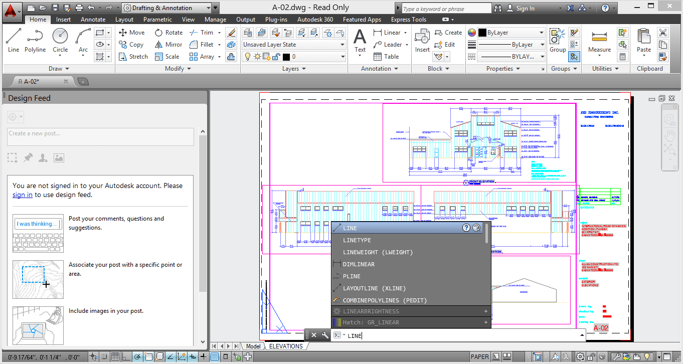
Command Line Enhancements
The command line has been enhanced to provide smarter, more efficient access to
commands and system variables. And, you can use the command line to find other content such as hatch patterns, visual styles, and internet help.
commands and system variables. And, you can use the command line to find other content such as hatch patterns, visual styles, and internet help.
AutoCorrect
If you mistype a command, instead responding with “Unknown command”, AutoCAD autocorrects to the most relevant and valid AutoCAD command. For example, if you accidently type TABEL, the TABLE command is automatically launched.
If you mistype a command, instead responding with “Unknown command”, AutoCAD autocorrects to the most relevant and valid AutoCAD command. For example, if you accidently type TABEL, the TABLE command is automatically launched.

To customize the AutoCorrect List click Manage tab > Customization panel > Edit Alias (flyout) > Edit AutoCorrect List.
The autoCorrectUserDB.pgp file will be opened. The syntax is as follow:
INCORRECT, *CORRECT
For example, if you consistently mistype BLOCK as BOLCK, enter
BOLCK, *BLOCK
The autoCorrectUserDB.pgp file will be opened. The syntax is as follow:
INCORRECT, *CORRECT
For example, if you consistently mistype BLOCK as BOLCK, enter
BOLCK, *BLOCK

AutoComplete
AutoComplete command entry is enhanced to support mid‐string search. For example, if you type SETTING on the Command line, the suggestion list displays commands containing the word SETTING anywhere within it, not just at the beginning.
AutoComplete command entry is enhanced to support mid‐string search. For example, if you type SETTING on the Command line, the suggestion list displays commands containing the word SETTING anywhere within it, not just at the beginning.

Adaptive Suggestions
Commands in the suggestion list are initially displayed in the order of their usage based on general customer data. As you continue to use AutoCAD, the order of commands in the suggestion list will adapt to your own usage habits. The command usage data is stored in the profile and adapts to each user.
Commands in the suggestion list are initially displayed in the order of their usage based on general customer data. As you continue to use AutoCAD, the order of commands in the suggestion list will adapt to your own usage habits. The command usage data is stored in the profile and adapts to each user.
%appdata%\Autodesk\AutoCAD 2014\R19.1\enu\Support\AcCommandWeight.xml
Synonym Suggestions
The Command line has a built in synonym list. Enter a word at the command line and it will return a command if a match is found in the synonym list. For example, if you enter Symbol, AutoCAD finds the INSERT command so you can insert a block. Or if you enter Round, AutoCAD finds the FILLET command so you can add a fillet to a corner.
The Command line has a built in synonym list. Enter a word at the command line and it will return a command if a match is found in the synonym list. For example, if you enter Symbol, AutoCAD finds the INSERT command so you can insert a block. Or if you enter Round, AutoCAD finds the FILLET command so you can add a fillet to a corner.

You can add your own words to the AutoCorrect and Synonym lists using the Edit Aliases tool from the Manage ribbon tab.
In the acadSynonymsGlobalDB.pgp file, enter the words in the following format:
SYNONYM, *COMMAND
For example, if want you BLOCK to be displayed in the suggestion list when you enter SYMBOL, enter
SYMBOL, *BLOCK
SYNONYM, *COMMAND
For example, if want you BLOCK to be displayed in the suggestion list when you enter SYMBOL, enter
SYMBOL, *BLOCK
Internet Search
You can quickly search for more information on a command or system variable in the suggestion list. Move the cursor over the command or system variable in the list and choose the Help or Internet icons to search for relevant information. The term AutoCAD is automatically prepended to the current term for searching the internet.
You can quickly search for more information on a command or system variable in the suggestion list. Move the cursor over the command or system variable in the list and choose the Help or Internet icons to search for relevant information. The term AutoCAD is automatically prepended to the current term for searching the internet.

Content
You can use the command line to access layers, blocks, hatch patterns/gradients, text styles, dimension styles and visual styles. For example, if you enter Door at the command line and the current drawing has a block definition with the name Door, you can see a preview of it and quickly insert it right from the suggestion list.
You can use the command line to access layers, blocks, hatch patterns/gradients, text styles, dimension styles and visual styles. For example, if you enter Door at the command line and the current drawing has a block definition with the name Door, you can see a preview of it and quickly insert it right from the suggestion list.

Here is what it look like for Hatch patterns.

Categories
To make the suggestion list easier to navigate, system variables and other content are organized into expandable categories. You can expand a category to see the results or press the Tab key to cycle through each category.
To make the suggestion list easier to navigate, system variables and other content are organized into expandable categories. You can expand a category to see the results or press the Tab key to cycle through each category.
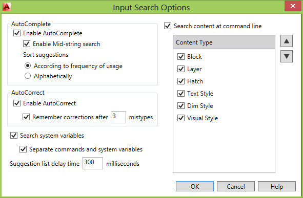
Input Settings
You can customize the behavior of the command line using controls in the Input Settings menu when you right‐click on the command line. In addition to the previous options to enable AutoComplete and search for system variables, you can enable AutoCorrect, Search Content and Mid‐string Search. All of these options are turned on by default.
You can customize the behavior of the command line using controls in the Input Settings menu when you right‐click on the command line. In addition to the previous options to enable AutoComplete and search for system variables, you can enable AutoCorrect, Search Content and Mid‐string Search. All of these options are turned on by default.

Another right‐click option provides access to the new Input Search Options dialog box.
Dynamic input also supports AutoCorrect, mid‐string search, AutoComplete, Synonym Suggestions and adaptive suggestions.
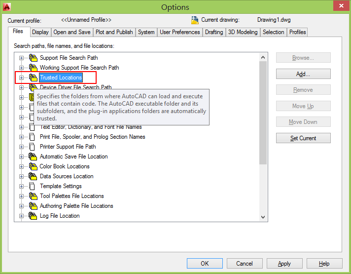
Binary Security
AutoCAD 2014 provides new controls to enhance software security and help prevent loading and running of unauthorized or malicious AutoLISP and VBA applications.
The Files tab of the Options dialog box includes Trusted File Search Path. You can also access these controls using the new TRUSTEDPATHS and TRUSTEDDOMAINS system variables.
The Files tab of the Options dialog box includes Trusted File Search Path. You can also access these controls using the new TRUSTEDPATHS and TRUSTEDDOMAINS system variables.
A security control on the System tab of the Options dialog box provides access to new Executable File Settings.
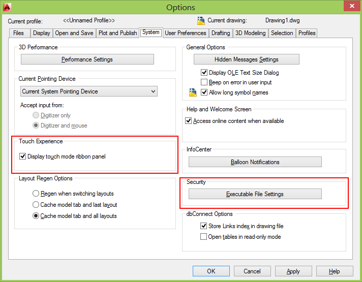

You can allow executable files to be loaded from all search paths or only from the trusted locations specified on the Files tab. And, you can choose to display a warning before loading executable files outside the trusted locations.
When Trusted Locations or TRUSTEDPATHS includes a folder that ends with \... (backslash and three dots), all of its subfolders are also trusted.
File Loading - Security Concern
An executable file was found outside of the specified trusted locations. What do you want to do? Make sure this file comes from a trusted source and does not contain malicious code.

These options are applied to the new SECURELOAD system variable.
Similar have been added to the Deployment Wizard enabling you to apply Secureload functionality to network deployments.
Similar have been added to the Deployment Wizard enabling you to apply Secureload functionality to network deployments.
File Tabs
Drawing tabs have been added and is a fast and visual way to switch between open drawings or to create new ones. You can turn the file tabs bar on or off using the File Tabs control on the View ribbon tab.

When File Tabs are turned on, a tab for each open drawing is displayed at the top of the drawing area. File tabs are displayed in the order they were opened. You can drag and drop tabs to change their order. If there is not enough room for all the file tabs to display across the area, an overflow menu at the right end of the file tabs bar provides access to the additional files.
A lock icon on a tab indicates that the file is open as read‐only and an asterisk indicates if the file has been modified since its last save.
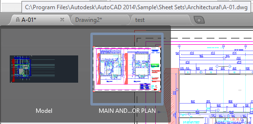
When you pass the cursor over a file tab, preview images of the model and layouts are displayed. If you pass the cursor over one of the preview images, the corresponding model or layout is temporarily displayed in the drawing area and Plot and Publish tools are accessible from the preview image.

The right‐click menu for file tabs enables you to create, open, save and close files including the ability to close all open files except the one on which you right‐clicked. You can also copy the full file path to the clipboard or open the file location in Windows Explorer.

A Plus (+) icon to the right of the drawing tabs, enables you to easily create new drawings, automatically adding their tabs as they’re created.
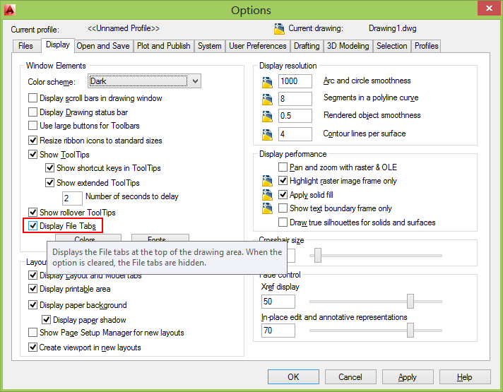
FILETAB command displays the File tabs at the top of the drawing area.
FILETABCLOSE command hides the File tabs at the top of the drawing area.
Display File Tabs is available in Options > Display.
Autodesk 360
In AutoCAD 2014 the Online ribbon tab is renamed to Autodesk 360. It includes a new Open Folder tool for easy access to the Autodesk 360 folder on your local machine and the new Design Feed enables you to enter posts and images for a drawing that can be shared online.
This is what it look like if the Autodesk 360 desktop companion is not installed and the commands are unavailable.

ONLINEOPENFOLDER command opens your local Autodesk 360 folder in Windows Explorer.
Design Feed
Design Feed, accessible from the Autodesk 360 ribbon tab, displays a palette in which you can enter text messages and attach images to be shared online with colleagues, clients, and consultants through Autodesk 360.

Posts appear with related drawings on the desktop, on the web, and across mobile devices. Turn on Design Feed from the Autodesk 360 ribbon tab.

You can associate your message with a location or area within the drawing. In the example below, the first post was associated with an area and indicated with a design feed bubble. The settings button on the Design Feed palette lets you control the display of the bubbles.

You can tag colleagues, clients, and consultants to notify them of your post; notifications will be sent to them by email and will also appear within AutoCAD.
After you finish creating a post, it is saved to your Autodesk 360 account with the drawing, along with any images that you attached. Using Autodesk 360, the people that you have authorized can view the drawing and its associated posts, and the people that you have tagged can post replies. When the questions in a post and its replies are no longer active, you can resolve the thread to hide it in the Design Feed palette.
After you finish creating a post, it is saved to your Autodesk 360 account with the drawing, along with any images that you attached. Using Autodesk 360, the people that you have authorized can view the drawing and its associated posts, and the people that you have tagged can post replies. When the questions in a post and its replies are no longer active, you can resolve the thread to hide it in the Design Feed palette.
DESIGNFEEDCLOSE command closes the Design Feed palette.
DESIGNFEEDOPEN command opens the Design Feed palette.
Geolocation
Support for Geographic locations has been significantly enhanced. It includes the same Coordinate System Library as AutoCAD Map 3D and new Autodesk Live Maps.
There are many benefits to defining a location in your drawing. When you import geolocated data into a geolocated drawing, AutoCAD transforms the data based on the drawing's geographic location. You can see your design within the context of its location and if you render the model, it will have the correct sun angle. If you export the drawing to a mapping service like Google Earth, it will automatically display at the correct location. When you insert geo‐referenced images or blocks into your geo‐referenced drawing, they are automatically placed in the correct location and at the correct scale. For example, imagine large projects that have multiple designers working separately on the same design, such as a housing project. If each designer uses the same coordinate system, all the drawings will insert at their appropriate locations when combined into a single file. You can mark specific point of interest in your drawings knowing that those points correspond to logical geographic locations. And, if you have a GPS device enabled on your computer, you can see your current position in the drawing and you can even mark positions as you walk around. For example, landscape architects can visit the site and take notes of the surroundings by marking them on the drawing. You can set a geographic location in your drawing using the Set Location tool on the Insert ribbon tab. Choose to set the location using Autodesk Maps Service or by selecting a KML or KMZ file.
There are many benefits to defining a location in your drawing. When you import geolocated data into a geolocated drawing, AutoCAD transforms the data based on the drawing's geographic location. You can see your design within the context of its location and if you render the model, it will have the correct sun angle. If you export the drawing to a mapping service like Google Earth, it will automatically display at the correct location. When you insert geo‐referenced images or blocks into your geo‐referenced drawing, they are automatically placed in the correct location and at the correct scale. For example, imagine large projects that have multiple designers working separately on the same design, such as a housing project. If each designer uses the same coordinate system, all the drawings will insert at their appropriate locations when combined into a single file. You can mark specific point of interest in your drawings knowing that those points correspond to logical geographic locations. And, if you have a GPS device enabled on your computer, you can see your current position in the drawing and you can even mark positions as you walk around. For example, landscape architects can visit the site and take notes of the surroundings by marking them on the drawing. You can set a geographic location in your drawing using the Set Location tool on the Insert ribbon tab. Choose to set the location using Autodesk Maps Service or by selecting a KML or KMZ file.

Autodesk Maps Service is automatically available from AutoCAD 2014 when you are signed into your Autodesk 360 account.
When specifying a geographic location from a map, you can search for an address or latitude and longitude. If multiple results are found, you can click on each one in the results list to view the corresponding map and you can display the map as road or aerial data.
When you find the correct location, you can drop a marker to select it. A pin is placed on the map and corresponding latitude, longitude, and time zone are automatically applied. You can move the pin or modify the location properties as needed. An icon to the right of the elevation unlocks the latitude and longitude for manual editing.

Collapse the Results panel to maximize the map and easily change between Road and Aerial displays.
AutoCAD assigns World‐Mercator as the default coordinate system or you can choose from a library of coordinate systems. The coordinate system defines the scale of the map.
The current drawing unit is automatically displayed in the Geographic Location dialog box or you can choose from a list of standard units. The inserted map is automatically scaled appropriately for the specified drawing units.
When a map is applied to a drawing it is always displayed below drawing geometry. Whether apply a geographic location using a map or by selecting a KML/KMZ file, the geolocation marker is displayed in the drawing at a point you specify and a new Geolocation tab is added to the ribbon.
The Geolocation ribbon tab includes tools for modifying the geolocation and map display. You can specify a different location using the Autodesk Map Service or by selecting a KML or KMZ file. Pick a new location and north direction to reorient the geo‐marker. Or, completely remove the location data and assigned coordinate system from the drawing.
Easily switch between aerial and road map or turn off the map display while still maintaining the geographic location and coordinate system data.
If you are working on a GPS –enabled laptop, you can use the Locate Me tool to identify your current location in the map.
If you are working on a GPS –enabled laptop, you can use the Locate Me tool to identify your current location in the map.
You can mark positions in the drawing by entering lat‐long data, using your current location (for GPS enabled devices), or by picking points. For each position, you can enter text to describe the position. The new GEOMARKPOSITIONSIZE system
variable controls the initial size of the marker. You can modify the size, contents, and other properties of selected position markers using the Properties palette.
variable controls the initial size of the marker. You can modify the size, contents, and other properties of selected position markers using the Properties palette.
Position Marker is a new object type. When listed it shows as POSITIONMARKER. Internal name seen for example with AutoLISP is AcDbGeoPositionMarker.
(0 . "POSITIONMARKER") ... (100 . "AcDbGeoPositionMarker")
(0 . "POSITIONMARKER") ... (100 . "AcDbGeoPositionMarker")
Reality Capture
Reality Capture enables you to take a 3D laser scan of an object, topography, a building or even an entire town and attach it to an AutoCAD drawing as point cloud data. You can then use it as a real‐world reference for your design work. This point cloud data is stored as thousands, even millions, of points in 3D space.

Autodesk ReCap is a separate application which enables you to create a point cloud project file (RCP) that references multiple indexed scan files (RCS). It is installed with AutoCAD 2014, by default and you can launch it from the Window’s Start menu or from the Autodesk ReCap desktop icon.
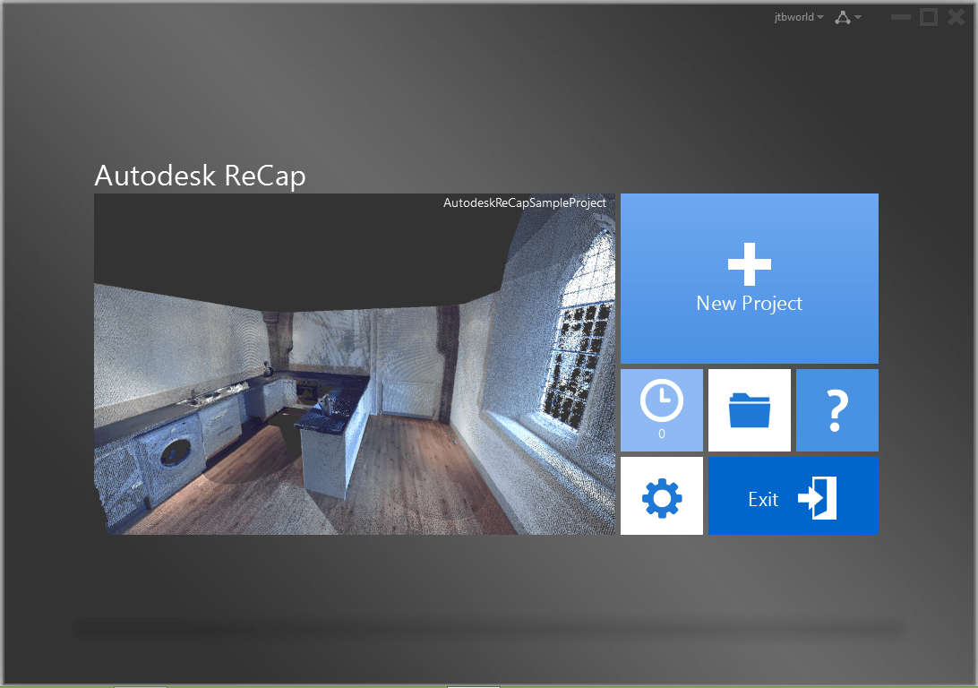
You can use Autodesk ReCap to convert scan file data to a point cloud format that can be viewed and edited in other products. Autodesk ReCap processes massive datasets enabling you to aggregate scan files and clean, section, spatially sort, compress, measure, and visualize them. The resulting high‐speed formats can then be used by AutoCAD and other Autodesk applications including Revit and Autodesk Inventor.
To use Autodesk ReCap, you must log into your Autodesk 360 account. In Autodesk ReCap, you can create a new project by selecting the scan files to import.
It supports scan data files from many popular formats including Faro, Leica, and Lidar just to name a few.
To use Autodesk ReCap, you must log into your Autodesk 360 account. In Autodesk ReCap, you can create a new project by selecting the scan files to import.
It supports scan data files from many popular formats including Faro, Leica, and Lidar just to name a few.
After selecting scan files to import, you can adjust import settings that affect the size and appearance of the point cloud. The imported files are displayed on the project screen where you can use a variety of tools to work with scan files.
The Home tile menu provides access to a variety of project‐related activities. You can save the current project as a Point Cloud Project file (RCP) or export it to a Point Cloud Scan file (RCS) both of which can be attached to AutoCAD drawings. You can import additional scan files into the current project or open a different project. A Preferences tool enables you to modify project settings and the Help tool provides detailed information about working with Autodesk ReCap.
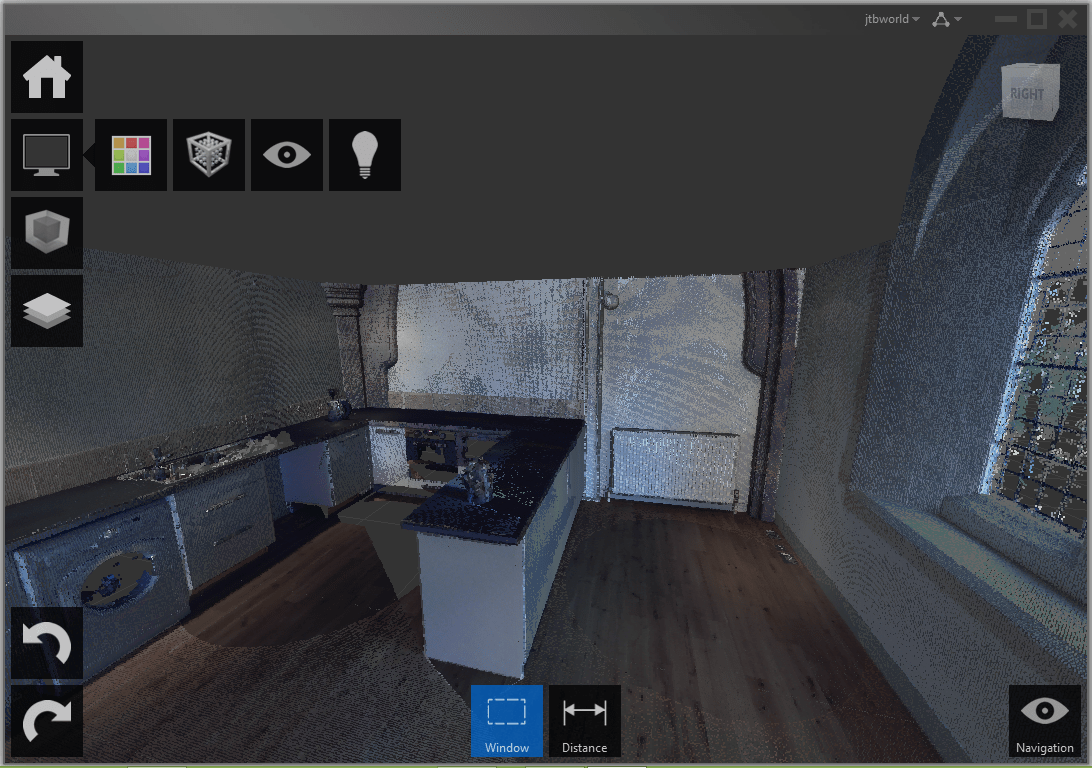
The Display Tools tile menu provides tools for analyzing the point cloud, changing its appearance, modifying the display of components in the work area, and specifying lighting options.
The Limit Box tile menu provides tools for working with limit boxes to define different volumes within the scene.
The Project Navigator tile menu provides one‐stop access to scan regions and individual scan files. The Project Navigator can remain attached to the Project tile menu so that it opens only when you hover over it or work within it. If you want to keep it open as you work, detach it from the tile menu and move it to a location on or off the program work area.
After producing point cloud files Autodesk ReCap, or if you’ve received files from someone else, you can attach them to your AutoCAD drawings.
After producing point cloud files Autodesk ReCap, or if you’ve received files from someone else, you can attach them to your AutoCAD drawings.
Point Cloud
Point cloud functionality is enhanced in AutoCAD 2014 to support inserting of Point Cloud Project (RCP) and Scan (RCS) files produced by Autodesk ReCap in addition to the previously supported PCG and ISD formats.
You can select point cloud files using the Attach tool from the Point Cloud panel of the Insert ribbon tab.
After a point cloud is attached, the contextual tab that is displayed when the point cloud is selected is enhanced to make it easier to work with point clouds. You can now change the stylization (colorization) of point clouds to colorize the point cloud based on the scan colors (colors captured by the scanner), object color (color assigned to object), Normal (colorize based on the normal direction of point) or Intensity (reflectivity value of points). If normal or intensity data was not captured with the scan, those stylizations are disabled. In addition, more clipping tools are displayed on the ribbon to make it easier to clip the point cloud.

AutoUpdate is turned off by default, preventing the point clouds from automatically updating every time the view is changed and improving performance when working with large point clouds. You can use the refresh button to manually update the point clouds.
Windows 8 touchenabled device
AutoCAD 2014 supports Windows XP, Windows 7 and Windows 8. If you are using a Windows 8 touchenabled device, you can benefit from smoother pan and zoom performance. A new control on the System tab of the Options dialog box displays a touch mode ribbon panel when a touch screen device is detected.
The Touch ribbon panel enables you cancel the current command and returns you to the Select/Command prompt.
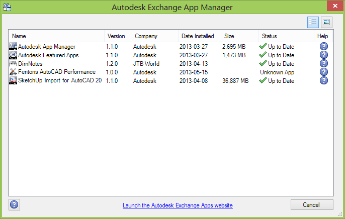
Exchange Apps
A default installation of AutoCAD 2014 adds several valuable apps from Autodesk Exchange including the Featured Apps ribbon tab, the Exchange App Manager and the Import SKP tool that imports a sketchup file into the current drawing as a block reference.

The Feature Apps ribbon tab provides easy access to the Exchange site where you can browse and download AutoCAD apps; some for free and some for purchase. It also includes a selection of featured apps that you can select and download directly from the Featured Apps tab without browsing through the entire Exchange site.
The Exchange App Manager and the Import SKP File tools are accessible from the Plug‐ins ribbon tab.
Use the Exchange Apps Manager to easily view and update installed apps. Double‐click on an app or choose Help from the right‐click menu to learn more about it. Just as easily uninstall or rate the app using the right‐click menu options.
Xref Manager
The display of linetypes and layers from externally referenced drawings is enhanced in AutoCAD 2014. Xref linetypes are not displayed in the linetype list of the ribbon or Properties palette. Xref layers are still displayed in the ribbon so you can control their visibility but they are not displayed in the Properties palette.
You can easily change the attachment type for an xref between Attach and Overlay by double‐clicking in the Type column.
A new option in the right‐click menu enables you to change the xref type for multiple selected xrefs at the same time.

The External References palette includes new tools to easily change the path of selected xrefs between Absolute and Relative. You can also remove the path completely.

The –XREF command includes a new PATHTYPE option enabling you to automate these path changes through scripting.
Arc Creation
Easily draw an arc in either direction using by pressing the Ctrl key to switch directions as you draw.
FILLET and CHAMFER of Polylines
Now the commands fillets or chamfers the first and last segments of an open polyline to create a closed polyline.
Sheet Sets
When creating a new sheet in a sheet set the CreateDate field stored in the associated template (.dwt) displays the creation date of the new sheet rather than the creation date of the template file.
Plot Styles
The CONVERTPSTYLES command enables you to convert the current drawing to either named or colordependent plot styles. In AutoCAD 2014 it is enhanced to support style names with spaces.
Layer Manager
The number of layers displayed on the ribbon has been increased.
Layers are now displayed using natural ordered sort. For example, the following layer names 1, 4, 25, 6, 21, 2, 10 are sorted as 1, 2, 4, 6, 10, 21, 25 instead of 1, 10, 2, 25, 21, 4, 6.
A new Merge option "Merge selected layer(s) to ..." in the Layer Manager enables you to select one or more layers from the layer list and merge the objects from those layers onto a different layer. The original layers are automatically purged from the drawing.

Materials Browser
There are some enhancement in the Materials Browser.
1. List of materials: each material has it’s own background stripe.
2. Added filtering of displayed materials from a bar.
3. New, more meaningful icon for managing libraries.
4. It is possible to show/hide library panel.
5. Added icon to show/hide library tree on the bar/command removed from drop down list.
6. New interface of material tree.
7. Added sorting by category to drop down list in Document Materials.
Dimensions
The new DIMCONTINUEMODE system variable provides you with more control when creating continued and baseline dimensions. When DIMCONTINUEMODE is set to 0, the DIMCONTINUE and DIMBASELINE commands create dimensions based on the current dimension style. When set to 1, they apply the dimension style of the selected dimension.
Text
Single line text is enhanced to maintain the last justification setting until it’s changed.
Adds Left to the Justification prompt options in the TEXT command.
TEXTJUSTIFY (System Variable) displays the default justification used by the TEXT command to create single-line text. Initial value: Left. This setting is changed by the Justify option of the TEXT command.
Annotation scale in the Select Annotation Scale dialog box is set only with a drop-down list (no direct entry).
Attributes
The default behavior for inserting blocks with attributes displays the dialog box. ATTDIA is set to 1.
Hatch
The Hatch tool on the ribbon maintains the previous method for selecting objects to hatch: Pick internal point or Select objects. The Undo option is added to the command line.
HPPICKMODE (System Variable) indicates whether the default method for identifying hatch areas is clicking enclosed locations or selecting boundary objects.
Raster Images
The display of and performance with raster images seems to have been improved when working with large image files.
Hardware Acceleration
The Hardware Acceleration icon has been updated.


The check engine light enhancements are a stronger suggestion to keep the video card files up-to-date on your computer. If you are up-to-date you will not notice it.
If you are not updated, you will see an orange icon on the tray (stands out) to indicate no video acceleration is being used and you will get a dialog explaining how to get the newest drivers and why they are important or that no video card is being used at all.
If you are not updated, you will see an orange icon on the tray (stands out) to indicate no video acceleration is being used and you will get a dialog explaining how to get the newest drivers and why they are important or that no video card is being used at all.
Loading of JavaScript
WEBLOAD command loads a JavaScript file from a URL, and then executes the JavaScript code contained in the file.
If you try to load a JavaScript file from an untrusted server, one that is not specified in the TRUSTEDDOMAINS system variable, a security warning will display.
Help
AutoCAD Help system enhancements:
Improved access to online Help, particularly when using proxy servers.
New search filters enable you to narrow your search results based on the type of user. For example, if you choose User, you can filter on commands and system variables. If you choose Developer, your filters include AutoLISP®, ActiveX, DXFTM, and .Net. The Administrator option includes Installing, Migrating, Customizing, and Administrating. You can choose All Content to filter on any combination of content.
The Hitchhiker’s Guide to AutoCAD Basics is included in the Resources section and has been updated for AutoCAD 2014. The image is now also clickable to quickly navigate to the main sections.
These are some great tools that i definitely use for SEO work. This is a great list to use in the future..
ReplyDeleteCeramic flooring